
Hardware design · 2027 season
Rocket family A–G
Design v19 · not printed or flown yet
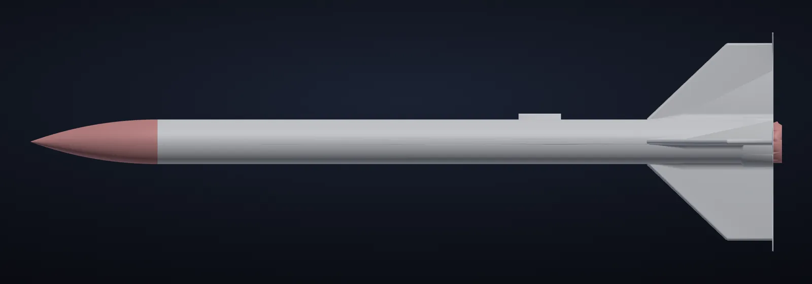
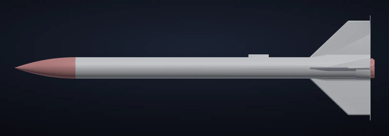
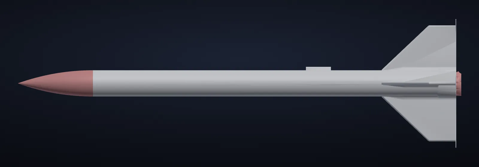
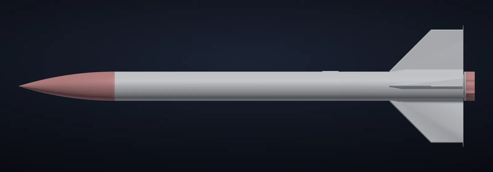
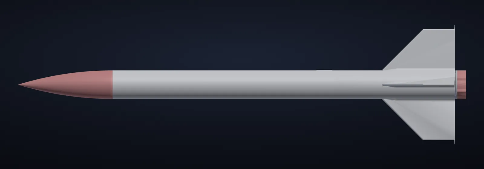
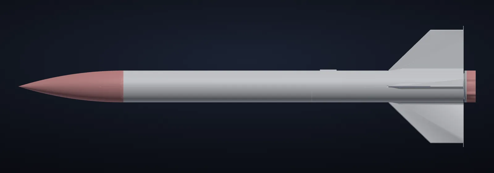
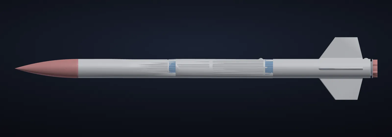
Seven 3D-printed model rockets, one for every motor class from A to G, all built on the construction of the original R02: harmonica walls with ribs and ring frames, fins printed with the body, motor locked both ways. Being prepared for the 2027 season – every class will be test-flown, with the goal of certification for each level.
All classes
Key figures (estimates)
| Class | Motor | Size | Mass | Stability (cal) | Apogee | Launcher |
|---|---|---|---|---|---|---|
| A | Estes A8-3 | 354 mm × Ø21 | ≈73 g | 2.1 | ≈50 m | 3 mm rod, min. 0.9 m – two launch lugs |
| B | Estes B6 | 354 mm × Ø21 | ≈78 g | 2.1 | ≈150 m | 3 mm rod, min. 0.9 m – two launch lugs |
| C | Estes C6 | 354 mm × Ø21 | ≈83 g | 1.9 | ≈390 m | 3 mm rod, min. 0.9 m – two launch lugs |
| D | Estes D12-5 | 561 mm × Ø36 | ≈234 g (with 8 g nose ballast) | 1.6 | ≈180 m | 5 mm rod, 1.2–1.5 m – two launch lugs |
| E | Estes E12-6 | 561 mm × Ø36 | ≈244 g (with 8 g nose ballast) | 1.6 | ≈380 m | 5 mm rod, 1.5 m – two launch lugs |
| F | AeroTech F42-8T | 606 mm × Ø42 | ≈345–375 g | ≈1.5 (earlier estimate, to be re-checked) | ≈510–545 m | 1/4" (6.4 mm) rod, 1.5 m – two launch lugs |
| G | AeroTech G80-7T | 1137 mm × Ø60 | ≈1.1–1.3 kg | ≈1.8–2.2 (earlier estimate) | ≈385–480 m | 1010 rail, 1.8–2.0 m – two M4 rail buttons |
Construction
Shared technology
- Harmonica wall (from the original R02): 1.0 mm skin with internal longitudinal ribs to 2.0 mm, plus 3 internal ring frames per tube. ≈18 % lighter than a plain 2 mm wall, protects the thin skin against dents and cracking layers. Outer diameter unchanged.
- Fins printed with the body (no glue, cannot fall off), 2.4–2.8 mm thick, with R4 concave fillets that fade smoothly into a fully rounded leading edge.
- Motor locked both ways: forward stop ring + screw-in retainer / threaded sleeve and nut – never just a friction fit.
- Two guide points on the launcher (two lugs or two rail buttons) so the rocket cannot rock on the rod.
- Estimated drag reduction from the rounded leading edges: ≈20–35 % of total Cd (semi-empirical estimate).
All figures are estimates from the 3D models (Barrowman method and a 1-D flight model) – nothing has been printed or flown in this version yet.